PRJ-05 · UCSC ECE 218 Mechatronics
Mech Filter Design: 2 kHz IR Beacon Detection
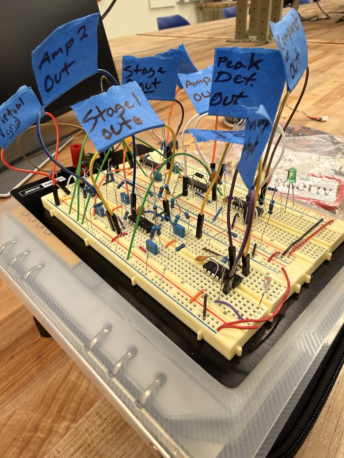
Outcome: Designed and characterized a multi stage active bandpass filter for detecting a weak 2 kHz IR beacon while rejecting nearby interference frequencies. I designed and tuned the filter, gain, and peak detection signal chain to reliably distinguish the target beacon across the competition field.
What I Did
- Designed an active bandpass filter around the approximately 2 kHz IR beacon frequency with a wider passband to tolerate beacon frequency variation.
- Built and tested multiple filter configurations before duplicating the two stage design into a four stage signal chain.
- Tuned non inverting gain stages with potentiometers between filter stages so the completed circuit could be adjusted after fabrication.
- Measured filter response using 5 mV and 50 mV input signals across desired and rejected frequencies to evaluate weak signal detection and out of band suppression.
Motivation
The robot needed to identify an opponent's IR beacon from across the competition field while rejecting nearby beacon and obstacle frequencies. The original detector was not sensitive enough at the required distance and was too dependent on an exact 2 kHz source, while physical beacons could vary by roughly 100 Hz. The redesigned circuit therefore required enough gain to recover a weak phototransistor signal while maintaining selectivity across an approximately 200 Hz target passband.
Results
Testing showed that increasing the filter from two stages to four substantially improved separation between the desired and rejected signals. With a 5 mV input, the four stage design produced approximately 233 mV at 2.0 kHz and 243 mV at 2.1 kHz. With a much larger 50 mV interference input, the same design produced only 9 mV at 1.5 kHz, 13 mV at 1.6 kHz, 38 mV at 2.4 kHz, and 20 mV at 2.5 kHz. The completed detector was able to produce a measurable response with the beacon approximately 25 to 30 feet away.
Technical Details
The detector began with four phototransistors feeding a transresistive input stage followed by a multi stage active bandpass filter designed around the 2 kHz beacon signal. The filter was developed using Analog Devices Filter Wizard with an approximately 200 Hz target passband to accommodate real beacon frequency variation. Two, three, and four stage configurations were characterized using biased square wave inputs representing both close range and long range phototransistor signals. Non inverting amplifiers with adjustable potentiometer gain were placed between stages, followed initially by an analog peak detector whose output was read by the microcontroller. After the peak detector failed during integration, the final filter stage was read directly and peak detection was moved into software.
- Role
- Circuit Design
- Team
- 3 Students
- Timeline
- 5 Days
- Context
- Analog Filters
- Tools
- Breadboard, op-amps, oscilloscope
- Skills
- Analog filter design · Op-amp stages · Signal characterization